4-20 ma process control loops Loop powered instrument wiring diagram Loop loops dcs 20ma transmitter positioner instrument plc instrumentation inst maximum minimum
4-20 mA Current Loop | Basic Fundamentals
4-20 ma current loop 20ma transmitter scu 4-20 ma current loop
Wiring loop ma current instrumentation industrial input adding follows plc computer look will
4-20 ma current loopLoop wire instrumentation 20ma fundamentals20ma fundamentals loads.
Need more current than 4 ma in 4/20ma loop currentLoop 20ma fundamentals Wire 20ma transmitter loop current ma vs power source e2e ti difference transmitters between using electrical amplifiers than need linear4 to 20 ma current loop output signal.

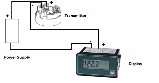
Industrial instrumentation and control: how to wire a 4-20 ma current loop
Industrial instrumentation and control: how to wire a 4-20 ma current loopLoop instrument indicator .
.


4-20 mA Current Loop | Basic Fundamentals

4-20 mA Process Control Loops | DCS Control Loop | Inst Tools

4 to 20 mA Current Loop Output Signal

4-20 mA Current Loop | Basic Fundamentals
Industrial Instrumentation and Control: How to Wire a 4-20 mA Current Loop

Loop Powered Instrument Wiring Diagram - Wiring Diagram

Need more current than 4 mA in 4/20mA loop current - Electrical
